News
What Is CAD and Why Is It a Critical Technology for CNC Machining?
Accurate engineering design is the foundation of every successful manufacturing process. In CNC machining processes, design quality directly affects the final result, production times, and costs. What exactly is CAD, how does it integrate into the manufacturing workflow, and how can proper engineering design save you money and prevent problems later on? All the answers.
What Is CAD (Computer-Aided Design)?
CAD stands for Computer-Aided Design. In practice, it is a technology that replaces the manual drafting methods traditionally used in engineering and industry—especially in the CNC world—and enables engineers and designers to create precise digital models of parts and components. Common software in this field includes SolidWorks, AutoCAD, and Inventor, with each program offering different capabilities suited to different types of projects.
Using CAD software, you can create 2D models for flat parts as well as 3D models for complex parts. A digital model created with CAD includes all the information required for manufacturing parts, including exact dimensions, tolerances, angles, radii, and complete geometry. This data serves as the basis for engineering design of components and industrial systems across diverse fields such as electronics, medical, and defense.
The main advantage of computer-aided design is the ability to make changes and corrections easily before production begins. With manual drafting, every change requires starting over. In contrast, with CAD technology, any update to a model parameter automatically updates all related elements. In addition, software can run simulations and visualizations that help identify issues even before building a physical prototype.
What Is the Role of CAD in Manufacturing Processes?
CAD design is performed at the start of the production chain, at the stage where an idea becomes a tangible model. The process begins by defining engineering requirements, moves on to designing the digital model, and then preparing the files for manufacturing. Every stage depends on the quality of the previous one, so investing in high-quality design leads to better results throughout the entire project.
Precise CAD design makes it possible to identify potential problems before manufacturing begins. For example, you may discover that a certain part cannot be manufactured due to problematic geometry, or because the tolerance requirements do not fit the selected manufacturing method. Early detection of issues saves costs associated with changes at later stages and prevents rejection of parts after production.
Beyond that, professional CAD design enables clear communication between all parties involved in the project. Misunderstandings and mistakes are reduced when engineers, procurement managers, production teams, and quality control staff work from the same accurate model.
Benefits of high-quality CAD design:
- Early identification of engineering issues before production begins.
- Cost savings by avoiding late-stage changes.
- Shorter production lead times thanks to optimal design.
- Improved communication between design and manufacturing teams.
- Full documentation of all design versions.
The Connection Between CAD and CNC Machining
CAD files are the basis for defining CNC machining setups. The CAD model serves as the foundation for the CAM process, where toolpaths and the code that runs the CNC machine are defined. Without a valid CAD file, the manufacturing process cannot begin.
The accuracy level of the CAD model directly affects the quality of the final part. If the model contains errors or missing details, they will carry into production and may lead to rejected parts or rework. Therefore, investing in high-quality design upfront pays off in the long run. Professional machining shops review CAD files before production in order to identify potential issues.
CAD design factors with potential impact on manufacturing:
- Tolerances: precise definition of allowable deviation ranges during machining.
- Geometry: building a part design that can actually be manufactured.
- Material: selecting a material that fits the chosen machining method as part of the manufacturing process.
- Finish: defining the required surface roughness level of the component.
In machining processes (manual or CNC), a wide range of materials can be machined, including metals (aluminum, steel, stainless steel, copper, titanium), engineering plastics, and composite materials. Material choice affects many design parameters such as wall thickness, corner radii, and cutting speeds.
Differences Between CAD and CAM in Design and Manufacturing
CAD and CAM are two different stages in the manufacturing process. CAD, as noted, is the engineering design of the part you want to produce, performed on a computer (as opposed to manual drafting). At this stage, the geometry, dimensions, and tolerances of the part are defined. CAM (Computer-Aided Manufacturing) takes place in the manufacturing process itself. At this stage, the machining toolpaths, cutting speeds, operation sequence, and the machine’s technical parameters are defined.
The output of the CAM process is not a model (as in CAD), but code in G-code, the programming language of CNC machines. The code contains all instructions for machine movements, spindle speeds, cutting depths, and additional parameters. CAM programmers optimize CNC machine operation to shorten production times and improve surface finish quality.
Comparison between CAD and CAM:
- CAD: designing the part by creating a model with dimensions and tolerances.
- CAM: planning the manufacturing process by writing G-code to program the CNC machining machine.
Which CAD Formats Are Common in Machining?
There are many CAD file formats, and it is important to know which format fits each type of project. Choosing the right format saves time and prevents issues when transferring CAM files to manufacturing. Different formats preserve different levels of information, meaning that converting between formats can cause loss of critical data.
Main formats:
- STEP: a universal 3D file format, suitable for most machining applications and supported by all systems.
- IGES: an older 3D file format, common in relatively older systems, less accurate than STEP.
- DXF/DWG: 2D file formats, suitable for processes such as laser cutting and 2D milling.
- Parasolid (x_t / x_b): advanced formats based on a geometric modeling kernel, especially common in advanced CAD systems and in the automotive and aerospace industries.
STEP is the recommended choice for 3D machining projects, thanks to its ability to preserve all geometric information and the fact that it is supported by all CAM systems. For less complex projects, DXF files are sufficient and sometimes even preferable due to their simplicity.
It is recommended to save the original CAD file in the software’s native format, and also export a copy in STEP format. This makes it easy to edit the design in the future while also providing the shop that will run your project with a universal file that can be opened in any system.
Common CAD Design Mistakes That Affect Manufacturing
Even experienced professionals sometimes make mistakes that are only discovered at the manufacturing stage. It is worth knowing the common mistakes so you can avoid them in advance and save delays and unnecessary costs.
Failing to define tolerances is a relatively common mistake. If a CAD model does not specify allowable deviation ranges, the shop must guess or contact you for clarification. Another mistake is designing geometry that cannot be manufactured in practice, such as grooves that are too narrow for the cutting tool, sharp corners without a radius, or holes that are too deep relative to their diameter.
Another common issue is missing details in the CAD model. It is important to go down to the smallest details and define parameters such as thread type (metric/inch, fine/coarse), surface finish, fiber direction in the material, and more. Any missing detail requires clarification and lengthens preparation time for production. It is recommended to use a Technical Data Sheet listing all required information.
Admati Agencies – Advanced Manufacturing Solutions
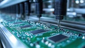
At Admati Agencies, we specialize in manufacturing components, sub-components, and sub-systems for the semiconductor, medical, and defense industries. We have decades of experience and provide full professional support from the initial specification stage through delivery of the finished product, including high-precision CNC machining services.
Our quality control department is equipped with advanced measurement tools to ensure compliance with required tolerances. We work according to ISO standards and maintain strict inspection processes throughout all production stages. Our accumulated engineering knowledge enables us to identify potential issues early and propose solutions that save time and money.
If you are planning a project that requires CNC-machined components, we will be happy to review your CAD files and provide professional feedback. Contact us for an initial consultation or to perform a feasibility review before production begins.
Questions and Answers About CAD and CNC Machining
What is the difference between CAD and CNC?
CAD software is used for engineering design and creating a digital model of the part intended for production. In contrast, a CNC machine performs the actual manufacturing through machining. The CAD file serves as the basis for defining the CNC machine via the CAM process.
Which format should I send CAD files in for manufacturing?
For 3D machining projects, a STEP CAD file is the recommended choice because it is universal and preserves all geometric information. For 2D machining projects, such as laser cutting, DXF files are suitable.
Do I need to define tolerances in the CAD file?
Yes, defining tolerances is critical. Without a clear tolerance definition in the CAD file, the shop does not know the required manufacturing accuracy. The result may be parts that do not meet requirements, or at minimum delays due to clarifications.
What is G-code and how is it related to CAD?
G-code is the programming language of CNC machines. The CAD file is converted in CAM software into G-code so the machine can understand the model and use it. The CAM process generates G-code containing all instructions for the machining machine’s operation.
What materials can be machined using CNC machining?
A wide range of materials can be machined with CNC, including metals (aluminum, steel, stainless steel, copper, titanium), engineering plastics such as PEEK and Delrin, composite materials, and even ceramics in certain cases.
How long does it take from having a CAD file to producing a finished part?
Production time depends on part complexity, the quantity to be produced, and the shop’s workload. A simple part can be ready within a few days, while a complex part with special requirements may take several weeks, including preparation and manufacturing time.
What happens if there is an error in the CAD file?
Errors in CAD files are usually discovered during CAM or when the file is reviewed before production. If errors are found, the shop contacts the customer to correct the file before manufacturing begins. If errors are identified early in the project, significant costs can be saved.
More News Articles